Ưu đãi trong tuần: Nhập mã UD50 giảm 50k cho đơn từ 300k!
Trang chủ
Menu

PCB Design with Proteus

Thiết kế PCB với Proteus

Thiết kế PCB với Proteus

Học thiết kế bảng mạch in với Proteus | Thiết kế PCB

4.7
(241 đánh giá)
889 học viên
Giảng viên
Daniel Haro
Phụ đề Việt chất lượng cao Phụ đề tiếng Anh Bán chạy Đánh giá cao
50.000đ 1.379.000đ -96%
✓ Xem giỏ hàng và thanh toán
Bao gồm phụ đề tiếng Việt, tiếng Anh
6.0 giờ video
75 bài giảng
Truy cập vĩnh viễn
Học trên mọi thiết bị
Cập nhật: 31/05/2026

Bạn sẽ học được gì

Thiết kế bảng mạch in với Proteus
Thiết kế PCB 1 hoặc 2 lớp
Hiểu toàn bộ quy trình thiết kế PCB
Tạo ký hiệu sơ đồ & thư viện
Tạo chân linh kiện & thư viện
Thêm mô hình 3D, tìm mô hình 3D mới
Cách đi dây PCB & Tự động đi dây
Lấy file sản xuất (Gerber, PDF)
Hiểu linh kiện PTH và SMD
Hiểu phần mềm Proteus cho thiết kế PCB

Yêu cầu

Kiến thức điện tử cơ bản
Phần mềm Proteus
Kiến thức máy tính cơ bản
Ham học hỏi

Đối tượng phù hợp

Nhà thiết kế PCB
Người chế tạo
Người đam mê điện tử
Người yêu thích điện tử
Người yêu điện tử
Người dùng Proteus

Nội dung khóa học

9 phần • 75 bài giảng
1 Tạo dự án mới
2 Giao diện người dùng & Điều hướng trong vùng làm việc
3 Chỉnh sửa khung tiêu đề
4 Chọn và đặt linh kiện từ thư viện Proteus
5 Linh kiện có mô hình mô phỏng
6 Thiết lập phím tắt
7 Quản lý linh kiện
1 Mạch sơ đồ nguyên lý
2 Tạo thư viện sơ đồ nguyên lý mới
3 Tạo đầu nối
4 Tạo điện trở
5 Tạo biến trở
6 Tạo bộ định thời 555
7 Kết nối sơ đồ nguyên lý
8 Thêm chế độ đầu cuối Tag
9 Hoàn thiện sơ đồ nguyên lý
1 Chuyển từ sơ đồ nguyên lý sang bố trí PCB
2 Thuật ngữ cơ bản về bố trí PCB
3 Tạo thư viện chân linh kiện
4 Tạo chân linh kiện cho điện trở
5 Tạo chân linh kiện cho biến trở
6 Tạo chân linh kiện cho diode Led
7 Tạo chân linh kiện cho đầu nối
8 Tạo chân linh kiện cho bộ định thời 555
9 Đặt các chân linh kiện
10 Tạo viền PCB
11 Quản lý quy tắc thiết kế
12 Tự động đi dây
13 Đi dây thủ công - Đường dẫn
14 Đi dây thủ công - Via
15 Giọt nước
16 Tạo mặt phẳng nguồn
17 Thêm chữ và logo
18 Đặt lỗ
1 Điều hướng 3D
2 Thêm linh kiện 3D
3 Thiết lập PCB 3D
4 Nơi tìm linh kiện 3D
5 Tải mô hình 3D (Step AP214)
1 Xuất PDF sơ đồ nguyên lý
2 Xuất PDF các lớp
3 PDF tùy chỉnh để in
4 Tạo file Gerber
5 Danh sách linh kiện - BOM
6 Trình xem Gerber của Proteus
7 Trình xem Gerber miễn phí - Gerbv
1 PCBWAY
2 Đặt hàng PCB trên PCBWAY
3 Nhận PCB
4 Xây dựng và kiểm tra PCB
1 Giới thiệu dự án thứ hai
2 Tạo dự án & Tạo thư viện sơ đồ nguyên lý
3 Tạo điện trở và biến trở
4 Tạo Diode Led, Led hồng ngoại và Phototransistor
5 Tạo tụ điện, chân cắm và bộ so sánh LM393
6 Hoàn thiện mạch sơ đồ nguyên lý
7 Chuyển sang bố trí PCB & Tạo thư viện chân linh kiện
8 Tạo chân linh kiện 0805 cho điện trở
9 Tạo chân linh kiện 0805 cho tụ điện
10 Tạo chân linh kiện 0805 cho Led
11 Tạo chân linh kiện cho Led hồng ngoại và Phototransistor
12 Tạo chân linh kiện cho biến trở 10k
13 Tạo chân linh kiện cho bộ so sánh LM393 SMD SOIC
14 Tạo chân linh kiện cho chân cắm nam
15 Viền PCB và đặt chân linh kiện
16 Đi dây PCB
17 Thêm mô hình 3D
18 Hoàn thiện PCB
1 Cảm ơn bạn đã tham gia khóa học này
1 CH1: Làm thế nào để mô phỏng, ví dụ với điện trở tự tạo?
2 CH2: Làm thế nào để tạo thư viện mới trong phiên bản Proteus 8.6 cao hơn?
3 CH3: File khoan & Flatcam
4 CH4: Lớp in lụa biến trở - Giải thích thêm
5 CH5: Mặt phẳng nối đất - Thông báo lỗi: "không thể tạo đường viền bo mạch kín..."
6 CH6: Làm thế nào để tạo thư viện trong phiên bản Proteus mới nhất (từ 8.7 - 8.11 trở lên)

Giới thiệu khóa học

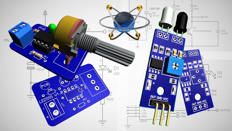
In this course We are going to cover all the necessary aspect to design a high quality printed circuit board. This is a step by step course.

We are going to start in the squematic circuit then the PCB layout and get the 3d visualization, also We are going to learn how to get the output files like PDF and Gerber files.

Let's get started¡¡¡


We will cover the complete process to design a PCB with Proteus, and see the below subjects


1. The use of Proteus as PCB Desing Software
Proteus is not just an Virtual Electronic Laboratory with different modules, in this course We are using Proteus as PCB Design software, since it has a powerful and dynamic interface.

We will learn:
   - How to navegate in the Proteus interface.
   - Understand the working methodology in Proteus.
   - The different files that We will create (Schematic & Footprint Library)


2. The Schematic & Schematic Library

In Proteus We can create an Schematic Library, where we are going to collect all our Projects schematic symbols. It is better to separate our Projects symbols from the Proteus Library Symbols. So in this way We can be sure about the components We are using, in additional when we are going to share our Project File everything will be well separated and idetificated.

We will learn:

   - How to create the schematic library.
   - How to create new schematic symbols.
   - How to use the schematic symbols from Proteus Library.
   - How to modify the schematic symbols from Proteus Library.
   - How to add the new symbols into our schematic library.
   - How to identify our schematic library and where to find it.
   - Complete our Schematic Diagram.

3. PCB Layout & Footprint Library
Once we complete our schematic diagram, We are going to pass to the PCB Layouy interface. Where we finally will make the layout of our project. After we complete this step, we can get all the out files to create our pcb.

We will learn:

   - How to create the Footprint Library.
   - How to create new Footprints and add them into our library.
   - How to modify the Footprint from Proteus Library.
   - How to identify our Footprint library and where to find it.
   - How to use the Autorouting option.
   - How to route our PCB ( 1 & 2 layers pcb)
   - Understand the PCB Layout terminology.


4. Visualization 3D
Proteus offers the 3d Visualization, which we can consider necesary, it will be kind of confirmation between our models and the real component. We add easly the 3d models and get our 3d PCB that we can share.

We will learn:

   - How to add 3d models.
   - How to Switch to the 3d view.
   - How to set the 3d pcb (Colors, visual options, Copper, 3d models)
   - Where to find new 3d models.
   - Which extension for 3d model we need to use.
   - Export our 3d pcb.

5. Manufacturer Files

The manfacturer files are the final files that we need to get from our Project, and with them we are going to create the pcb in real. Process will provide these information after we complete the layout of our pcb.

We will learn:

   - How to get the Gerber Files.
   - How to get the PDF files (Top and Bottom Copper layer )
   - How to order our PCB from PCB factory.
Khóa học liên quan

Khám phá thêm các khoá học cùng chủ đề

Hiển thị tất cả khoá học Electrical Engineering
Hiển thị tất cả khoá học Electronics
Hiển thị tất cả khoá học Pcb Layout
Hiển thị tất cả khoá học Proteus
Zalo
Tôi có thể tư vấn khoá học cho bạn 😊